Troubleshooting the 'avrdude: stk500_getsync()' Error on Arduino Uno
Resolve the common 'avrdude: stk500_getsync()' error on Arduino Uno boards. This guide covers port conflicts, RX/TX interference, driver issues, and hardware loopback testing.
26 Aug 2025, 17:00 UTC
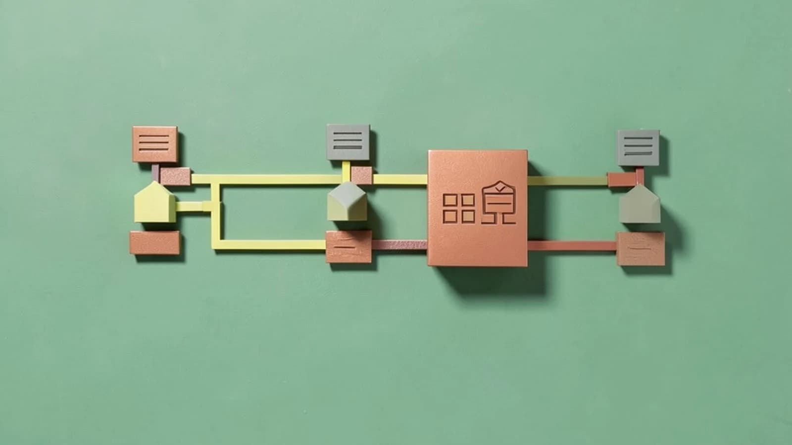
The Communication Handshake Failure
The avrdude: stk500_getsync() error is a generic communication failure. It occurs when the Arduino IDE (the host) sends a request to start the upload process, but the bootloader (the small piece of software on the ATmega328P chip) does not respond within the expected timeframe.
Because this is a "timeout" error, it does not tell you why the connection failed, only that it did. The solution usually involves isolating whether the break is in the software configuration, the physical cable, or the hardware circuitry.
Diagnostic Matrix
| Symptom | Likely Cause | Primary Check |
|---|---|---|
| Port menu is greyed out | Driver or Cable failure | Device Manager / System Profiler |
| Port is selected but upload fails | Wrong Board/Processor selected | IDE Tools Menu |
| Upload fails only with sensors attached | RX/TX Pin interference | Physical wiring on Pins 0 and 1 |
| Board is recognized but won't sync | Corrupted Bootloader | Loopback Test |
Step-by-Step Resolution Path
1. Verify Software Configuration
The IDE must be configured to match the hardware exactly, as the baud rate (the speed of data transmission) is hardcoded into the bootloader.
- Board Selection: Go to
Tools > Board. Ensure Arduino Uno is selected. Selecting a Nano or Mega will use the wrong communication protocol. - Port Selection: Go to
Tools > Port. If multiple COM ports are listed, unplug the Arduino and see which one disappears; the remaining one is not your board.
2. Clear Serial Interference
The Arduino Uno uses Digital Pins 0 (RX) and 1 (TX) for USB communication. If you have components—such as Bluetooth modules, GPS, or MIDI controllers—connected to these pins, they will fight the IDE for control of the serial line.
- Power off the board.
- Disconnect all wires from Pin 0 and Pin 1.
- Attempt to upload a basic
Blinksketch.
3. Driver and Hardware Validation
Official Arduino boards use a specific USB-to-Serial chip, but many "Clone" boards use the CH340 chip. These require a separate driver installation to be visible to the OS.
- Windows: Check
Device Manager > Ports (COM & LPT). If you see "USB2.0-Serial" with a yellow warning triangle, install the CH340 driver. - macOS: Check
System Information > USBto see if the device is recognized at the hardware level. - Cable Check: Replace the USB cable. Many cables provided with cheap electronics are "power-only" and lack the data lines required for programming.
4. The Loopback Test (Hardware Isolation)
If the IDE sees the port but cannot sync, you need to determine if the USB-to-Serial chip is dead or if the ATmega328P microcontroller itself is the problem. A loopback test bypasses the microcontroller.
- Disconnect the board from power.
- Use a jumper wire to connect RESET to GND (this disables the main processor).
- Use another jumper wire to connect RX (Pin 0) to TX (Pin 1).
- Connect the board to the PC and open the Serial Monitor in the IDE.
- Type any character and press Enter.
Expected Result: If the USB chip is working, the character you typed will be echoed back to you in the window. If nothing returns, the USB-to-Serial hardware is faulty.
Escalation: Bootloader Recovery
If the loopback test passes but you still receive stk500_getsync(), the bootloader on the ATmega328P may be corrupted. This is a state where the chip is healthy, but it has "forgotten" how to accept new code via USB.
Requirement: You cannot fix a bootloader using the same board. You will need either an AVR ISP programmer or a second working Arduino configured as an "ArduinoISP".
Risk: Incorrect wiring during ISP flashing can permanently damage the microcontroller. Ensure the board is powered down before connecting the ISP header.
Verification of Fix
To confirm the issue is resolved, upload the Blink example (File > Examples > 01.Basics > Blink). If the onboard LED (marked 'L') begins to flash, the handshake is successful and the communication path is clear.
 arduino
0 replies
A thoughtful contribution can make all the difference. Be the first to share one.