Optimizing Parts with Fusion 360’s Generative Design: A Practical Guide
Discover how Fusion 360’s Generative Design automatically explores topology variations to cut part weight by up to 30% while keeping strength. Follow a step‑by‑step workflow, see a concrete example, and weigh the trade‑offs.
25 Sept 2025, 09:05 UTC
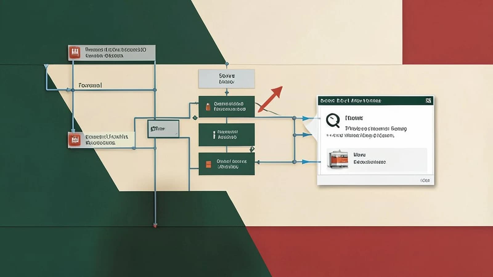
Why Generative Design Matters for Engineers
When a part must be lightweight yet strong, designers traditionally iterate through dozens of sketches, manual cuts, and stress tests. Autodesk Fusion 360’s Generative Design feature flips that process on its head: it automatically explores millions of topology variations to satisfy user‑defined goals such as weight, strength, and material usage. The result? Parts that can weigh up to 30 % less while still meeting the same load capacity.
Setting Up a Generative Design Project
Below is a concrete, step‑by‑step workflow that you can follow in Fusion 360. The example uses a simple bracket, but the same steps apply to any part.
- Create a Base Geometry
- Open Fusion 360 and start a new design.
- Sketch a rectangular plate (e.g., 100 mm × 50 mm × 5 mm).
- Extrude to create the solid body.
- Define the Generative Design Workspace
- From the Design workspace, click Generative Design > New Project.
- Import the base geometry as the “Design” element.
-
- In the workspace, add a Load by selecting the bracket’s top face and applying a uniform pressure (e.g., 5 MPa).
- Add a Fixation on the bottom face to simulate a mounting point.
- Optionally, add a Constraint that limits the part’s maximum thickness to 5 mm.
-
- Open the Material Library and select Aluminum 6061 for the base material.
- For the optimizer, enable the Alloy library so it can suggest other alloys if they meet the constraints.
-
- Set the primary objective to Minimize Weight.
- Add a secondary objective: Maximize Strength (ensuring peak stress < yield strength).
- Optionally, add a cost objective to keep material cost under a threshold.
-
- Click Generate. The cloud engine will iterate, producing a set of candidate parts.
- Use the Preview pane to compare candidates side‑by‑side.
-
- Choose the candidate that meets your weight and stress targets.
- Use the Refine tool to tweak geometry locally if needed.
-
- Export the chosen design to a STEP file for CAM machining or directly to a 3D‑print STL.
- Use the built‑in CAM workflow to generate toolpaths or send the STL to a slicer.
Checking the Results
After selecting a candidate, verify its performance:
- Open the Analysis tab and view the Stress Plot. Peak stresses should be below the yield strength of the chosen material.
- Use the Weight metric in the Generative Design workspace to confirm the weight reduction (e.g., 28 % less than the original bracket).
- Export a Report that lists material, weight, and stress data for documentation.
Trade‑offs and Limitations
- Compute Resources: Generative Design relies on a cloud‑based optimization engine. Large assemblies or complex load cases can consume significant CPU/GPU time, potentially leading to long wait times on standard workstations.
- Cloud Quota: Free or low‑tier Fusion 360 accounts have limited cloud compute credits. Exceeding the quota can throttle performance or incur additional charges.
- Design Intent: The optimizer may produce unconventional geometries that are difficult to machine or assemble. Engineers must review manufacturability and apply local refinements.
- Material Library Coverage: While the feature supports many alloys, composites, and polymers, the library may not contain every material a company uses. Custom material definitions can be added but require manual input of properties.
Next Steps for Engineers
- Experiment with Custom Objective Functions to balance cost, environmental impact, and performance.
- Integrate the optimized part into a larger assembly and re‑run the analysis to ensure system‑level constraints are met.
- Use the CAM integration to generate toolpaths directly from the candidate geometry, reducing the translation step.
- For rapid iteration, consider scripting the workflow with Fusion 360’s API to automate the creation of load cases and material assignments.
- Document the design process and results in a report for stakeholders, highlighting the weight savings and performance retention.
Conclusion
Fusion 360’s Generative Design turns a labor‑intensive design cycle into a data‑driven, automated process. By defining clear objectives and constraints, you can unlock topology optimizations that shave weight while preserving strength—often in a single workflow. The main trade‑offs involve compute time and the need for post‑processing to ensure manufacturability. With careful planning and validation, engineers can harness this powerful tool to accelerate product development and achieve superior part performance.
 fusion