Architecting VM Persistence in Harvester: KubeVirt and Longhorn Integration
Harvester blends KubeVirt and Longhorn to give VMs the mobility of containers while preserving persistent storage. Learn how the architecture keeps VM data safe across node failures, how to verify the integration, and when to shift to external storage for low-latency workloads.
06 Aug 2026, 04:50 UTC
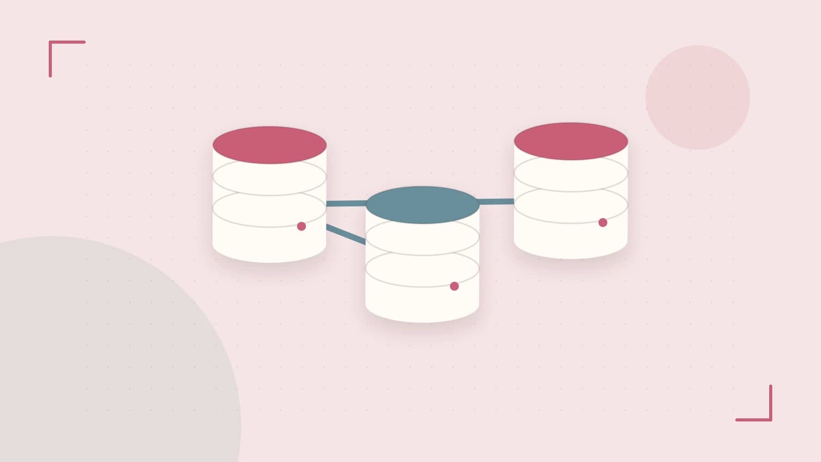
The Challenge: Bridging State and Orchestration
Traditional virtualization relies on a centralized Storage Area Network (SAN) or Network Attached Storage (NAS) to ensure that a Virtual Machine (VM) can move between hosts without losing data. In a hyperconverged infrastructure (HCI) like Harvester, the goal is to eliminate the external SAN while maintaining the same mobility and persistence. The core problem is mapping the stateful nature of a VM disk to the inherently transient nature of a Kubernetes pod.
The takeaway: Harvester solves this by wrapping KubeVirt—treating VMs as pods—around Longhorn, which aggregates local disks into a distributed block device. This allows the Kubernetes scheduler to move a VM across nodes while the storage layer ensures the data follows the compute.
The Minimal Design for High Availability
To achieve a functional, resilient environment, the smallest suitable design is a three‑node cluster. While a single node can run Harvester, it creates a single point of failure for both the control plane and the data layer.
Component Roles
- KubeVirt: Acts as the translation layer. It creates a "launcher" pod that manages the QEMU/KVM process. To the Kubernetes API, the VM is just another pod with specific resource requests.
- Longhorn: Provides the distributed block storage. It aggregates local disks across the nodes into a virtual pool and replicates data synchronously.
- Kubernetes Scheduler: Manages the placement of the VM pod based on CPU and memory availability, unaware of the underlying virtualization but aware of the storage requirements.
Trust and Data Boundaries
Harvester maintains a strict boundary between the Management Plane and the Guest Network. The management plane handles the Kubernetes API, Longhorn replication traffic, and cluster health. Guest networks are isolated via a Container Network Interface (CNI), ensuring that a compromise of a VM guest cannot easily pivot to the cluster's control plane.
Data Flow Boundary
When a VM writes to its disk, the data does not go directly to a local physical drive. It passes through the KubeVirt process to the Longhorn volume engine, which then replicates the write across the network to other nodes before confirming the write as successful. This ensures that if the primary node hosting the VM fails, the data exists in an identical state on a peer node.
Operational Configuration and Verification
To verify that the storage and compute layers are correctly integrated, you must inspect the relationship between the VM and its underlying pod. Run these checks from the Harvester management shell (SSH) with cluster-admin permissions.
Verifying VM-to-Pod Mapping
# List all virtual machine instances
kubectl get virtualmachineinstances -n harvester-system

# Find the pod associated with a specific VM
kubectl get pods -n harvester-system | grep virt-launcher
Expected Result: You should see a virt-launcher pod for every running VM. If the pod is missing or in CrashLoopBackOff, the VM will not start regardless of the dashboard status.
Storage Health Check
Access the Longhorn UI (integrated into the Harvester dashboard) and verify the Replica Count. A healthy production VM should have a replica count of 3. If the count is 1, the VM is tied to a single physical node, and a node failure will result in total data loss for that instance.
Failure Modes and Recovery
The architecture is designed to handle specific failure conditions, but each has a different recovery path:
| Failure Scenario | System Response | Recovery Mechanism |
|---|---|---|
| Single Node Crash | KubeVirt detects pod loss; Longhorn marks replica as failed. | Kubernetes reschedules the virt-launcher pod to a healthy node; Longhorn attaches the remaining healthy replicas. |
| Network Partition | Longhorn may enter a read-only state to prevent split-brain. | Manual intervention or automated quorum resolution to promote a new primary replica. |
| Disk Failure | Longhorn detects I/O error on a specific replica. | Longhorn automatically rebuilds the missing replica on another available node using the remaining healthy copies. |
Design Limitations and Evolution
This architecture assumes a high-speed physical network interconnect. Because Longhorn performs synchronous replication, the latency of the physical network directly impacts the disk I/O performance of the VM. If you observe high iowait in the guest OS, the network is likely the bottleneck.
When to change this design: If your workload requires sub-millisecond disk latency that distributed block storage cannot provide, you must move away from the HCI model and integrate an external NVMe-over-Fabrics (NVMe-oF) storage array, bypassing Longhorn for those specific high-performance volumes.
Rollback and State Change
Changing the replication factor of a volume in Longhorn is a state-changing operation. If you increase the replica count from 2 to 3 to improve resilience, Longhorn will begin a network-intensive synchronization process.
Rollback: To revert, reduce the replica count in the Longhorn UI. This will delete the most recent replica and stop the synchronization traffic, returning the cluster to its previous resource utilization state.
 harvester
0 replies
A thoughtful contribution can make all the difference. Be the first to share one.